Categories
DESCRIPTION
Product Overview
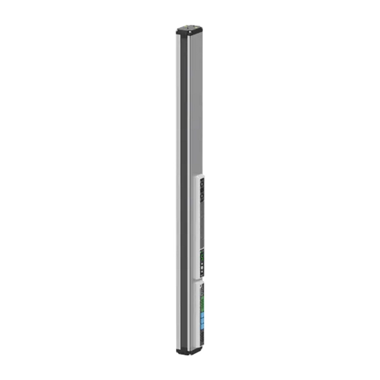
The BWML series line beam mapping sensors are designed to minimize non-detection areas, utilizing advanced line beam detection technology. These sensors offer easy installation by eliminating the need to precisely align the optical axis with the glass substrate. Supporting both CC-Link and EtherCAT communication protocols, the BWML series sensors enhance convenience and reliability with their diffuse reflective type design, making them an ideal solution for accurate glass substrate detection.
Key Features
- Stable Detection: The BWML series ensures reliable detection of glass substrates with minimal non-detection areas, thanks to its innovative line beam detection technology.
- Customizable Options: Users can choose from various configurations, including sensing channels (from 4 to 62 channels), sensing target pitch (minimum 20 mm), and sensing area (280 mm to 1,775 mm).
- EtherCAT Communication: The sensors support EtherCAT communication, a registered trademark and patented technology licensed by Beckhoff Automation GmbH, Germany.
- Easy Installation: Installation is simplified with an instruction mode and background sensing mode, allowing for a hassle-free setup.
- Advanced Features: The BWML series is equipped with a channel interference alarm, 5-stage sensing level setting, and emitter/receiver error alarms to ensure operational reliability.
- Bright Indicators: Multiple bright status indicators provide clear visual feedback on the sensor’s status.
Ordering Information
- Sensing Target Pitch: The optical axis pitch starts from 20 mm, customizable based on specific requirements.
- Sensing Channels: Available configurations include 4 to 62 sensing channels.
- Operation Mode: Choose between Light ON or Dark ON operation modes.
- Channel Orientation: Configurations can be set to either forward (bottom = 1 CH) or backward (top = 1 CH) orientations.
Product Components
- Included Items:
- Sensor unit
- Instruction manual
- Bracket A (4 pieces)
- Bracket B (4 pieces)
- Fixing bolts (8 pieces)
Dimensions
The length of the product varies according to the ordered specifications, corresponding to the maximum sensing area. The brackets provided with the sensor are designed to ensure proper installation and stability.
Unit Descriptions
- Output Indicator (Red LED): Displays the output status.
- Stability Indicator (Green LED): Indicates the stability of the sensor.
- Status Indicator (Tri-color LED): Shows various operational states using green, yellow, and red lights.
- Status Display: Provides real-time visual feedback on the sensor’s operational status.
- Mode Setting Key: Allows users to switch between different operational modes.
- USB Port: Used for firmware upgrades and mode changes, not intended for regular operation.
- Communication Status Indicator: LED that reflects the current communication status.
- Power Cable Connector: Connection point for the sensor’s power supply.
- EtherCAT Communication Input/Output Connector: Facilitates communication through EtherCAT, with an LED indicator to show communication status.

